This posting continues my exploration of the performance of my multi-band dipole as
reported earlier. Based on suggestions from KE4ID, I revised my antenna to the following specs:
- 102 ft total length of horizontal portion (previously 110 ft)
- 91 ft of 450-ohm ladder line (previously 84 ft)
- DX Engineering 1:1 balun (also tested with LDG 1:1 balun on 80 m band)
- 12 ft of 50-ohm coax to the antenna tuner
Update: Ultimately, I may need to change the feed line to 300-ohm ladder line. The current configuration is an attempt to reuse the 450-ohm line that fed my original 80 m loop at this location. Due to the loss of one of my corner support trees, I reconfigured the antenna materials to a dipole. The recommended feed line for a multi-band shortened dipole, used with a tuner, is 300-ohm ladder line.
The graph below shows the SWR vs frequency as measured with my antenna analyzer across the range of 3 to 30 MHz. The wide
variation of SWR is an indication of the
complexity of the overall antenna system. Also shown (as discrete points) are SWR data for selected frequencies on the transceiver side of the antenna tuner. These points show that the tuner is able to present reasonable SWR to the transceiver on most of the frequencies I sampled. An area of challenge is the 3.5 to 4 MHz band. The next graph shows this frequency range more closely.
 |
| SWR - 3 to 30 MHz |
The graph below shows the frequency range of 3.5 to 4 MHz. Along with the same SWR data measured by the analyzer there are two sets of SWR points from the transceiver side of the antenna tuner. Testing with the LDG 1:1 balun provided better results than the DX Engineering 1:1 balun at the lower end of the frequency band. Similar high SWR results at the low end of the band were also obtained with the previous configuration of the antenna and feed line.
 |
| SWR - 3.5 to 4 MHz |
The power efficiency of this antenna system (as built) is unknown. Instrumentation on the antenna side of the balun might reveal how much power or current is outbound to the antenna, and how this design compares with resonant antenna designs.
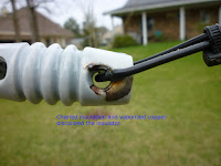
While adjusting the overall length of the antenna from 110 ft to 102 ft, I had the opportunity to notice lightning-caused damage from last summer's event reported
here. The two photos below show the effects at the western end of the antenna. Click on each image for the full size view.


No comments:
Post a Comment